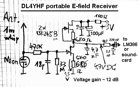

One of the most important features of Steve's design was a FET input for

McGreevy's design (linked below) I was able to design my own I do not know my RF very well, but looking at Stephen P. That is the main circuitĪnd it is up to you to add a power LED, headphone jack, power switch, and other bells and whistles as To a volume control R3 and then to the well known LM386 audio amplifier IC. Of the low frequencies (trying to get rid of some unwanted 60HZ signal). The signal is then passed on to U1B to filter out some The links areĬ3 and C7 pass high frequencies to ground that were picked up by the antenna.Īnd get amplified slightly (gain=1+(2.2K/1K). The correction is : R6 should go to the other end of C5, where it connects to the + input of the TL082. Note that there is an error in the schematic.
VLF RECEIVER DIY PDF
You can view the schematic of my circuit in either the PDF format (preferred) or as a. Were received in remote locations after many hours of listening. "whistler" (a several second tone decreasing in frequency) right away. Don't be disappointed if you don't hear a Some of the links below have sound files of VLF "signals". To pickup from the North and South you would have to point the ends of your antenna to the East and West.This VLF (very low frequency) receiver is used to pick up natural occurring low frequency radio waves created by nature. There is no signal pickup from the North or South. Looking down from above with the ends of the antenna pointing North and South, just like a compass would, the directions of best reception are EAST and WEST as shown by the circles in the chart above. These antennas exibit a bi-directional reception pattern as shown above. This project is an un-tuned wideband VLF receiver so no tuning capacitor is needed. The receiver will go down to 1 Hertz, but you will have to increase the capacitor values and use many turns of wire (more than 2000) to get there. You may want to change C1 and C2 depending on the exact tone quaility you prefer. See antenna directional signal pick up diagram at bottom of this page. If the antenna is mounted vertically this will allow hearing local underground radio signals (from earthquakes), and eleminate all of the distant lightning static noise, including any tweeks and whistlers. VLF waves can travel through the Earth's soil and underground rivers.

But this cutoff does not mean that nothing can be heard below 1600 Hz. The ionosphere propagation cutoff is approximately 1600 Hertz, which results in the "ping" sound of tweeks. This is the audio frequency range of the tweeks and whistlers. Tweeks travel EAST and WEST (mostly) so point the ENDS of the ferrite rod antenna NORTH and SOUTH so the flat broadside will pick up.įor best results use a "mid-range" type Hi-Fi speaker designed for the frequency range of 1000 Hertz through 5000 Hertz. Whistlers travel NORTH and SOUTH along the Earth's magnetic field lines so point the ENDS of the ferrite rod antenna EAST and WEST so the flat broadside will pick up. Whistlers and Tweeks are best heard after 9 PM your local time. Sudden LOUD feedback squeeling sound possible! If the unit squeels then you forgot to place R1, or the Antenna is too close to the speaker.Īdjust TONE Switch (SW1) as needed for most pleasing sound or signal strength.ĭo NOT use headphones or earphones, sudden very loud sound possible. It can be located a few feet above ground level away from power lines. Feedback squeel will result.Īntenna can be located remotely outdoors away from powerline noise by using microphone cable or twisted pair.Īntenna does not need to be up high for good reception. Keep the antenna 12 inches or more away from the speaker or speaker leads. WARNING! Do NOT use headphone or earphones. Use a "mid-range" type Hi-Fi speaker designed for the frequency range of 1000 Hertz through 5000 Hertz. SPKR: Any 8 ohm, 12 ohm, or 16 ohm Speaker greater than 3 inches diameter. Optional 200 ohm volume control resistor. VR1 (part not labled in diagram near speaker). Lower resistor values cut higher frequencies and general sensitivity. Adjust value higher or lower for best overall "tone". Q1, Q2, Q3, Q4, Q5: STORMWISE PART # 2N4124 NPN Transistors. The unit can be tuned by placing a capacitor across the antenna leads, but this will distort the pleasing sounds of the natural radio waves. The unit allows wide band (untuned) reception and features Hi-Lo tone control switch (SW1). This 5 transistor VLF receiver will drive a speaker. Listen to Whistlers, Tweeks, Auroras, Earthquakes, and other natural events that create VLF radio waves in the range of 100 Hertz - 10000 Hertz. This circuit is shown as an educational example only. There is no technical help with the projects. The following information is for educational and experimental uses only. (903) 383-7047 Build an VLF Whistler Receiver Home


 0 kommentar(er)
